Wednesday, October 30, 2013

Using Sonar Sensor with the Raspberry PI

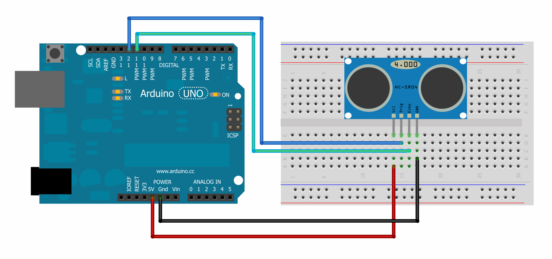
In this post I'm going to use the same Sonar sensor from the last blog post with the Raspberry PI and use python for measuring distance of objects. Just like interfacing with the Arduino you need to connect the Sensor to +5v and Gnd to the Raspberry PI. I'm using GPIO pins 24 and 25 to connect my sensor's trigger and echo pins. As a reference loook at the following image for the GPIO pinout of the PI.

The following code interfaces the sensor with the Raspberry PI. The original code can be found at (http://www.raspberrypi.org/phpBB3/viewtopic.php?f=37&t=40479) and there is another excellent example with code at (http://www.raspberrypi-spy.co.uk/2012/12/ultrasonic-distance-measurement-using-python-part-1/).


#Sonar interface with the Raspberry PI
 
#Import Python libraries
import time
import RPi.GPIO as GPIO


GPIO.setmode(GPIO.BOARD)

GPIO_TRIGGER = 18    #GPIO_24
GPIO_ECHO = 22        #GPIO_25

#Set Pins as output and input
GPIO.setup(GPIO_TRIGGER,GPIO.OUT) # Trigger
GPIO.setup(GPIO_ECHO,GPIO.IN) # Echo

#Set Trigger low
GPIO.output(GPIO_TRIGGER, False)

#Allow module to settle
time.sleep(0.5)

def sonar(n):
    #Send 10us pulse to trigger
    GPIO.output(GPIO_TRIGGER, True)
    time.sleep(0.00001)
    GPIO.output(GPIO_TRIGGER, False)
 
    while GPIO.input(GPIO_ECHO)==0:
        start = time.time()
       
    while GPIO.input(GPIO_ECHO)==1:
        stop = time.time()

    #Calculate pulse length
    elapsed = stop-start

    #Distance pulse traveled in that time is time
    #multiplied by the speed of sound (cm/s)
    distance = elapsed * 34000

    #That was the total distance so half it for reaching the object
    distance = distance /2

    return distance

while True:
    time.sleep(0.3)

    distance = sonar(0)
    print distance

   
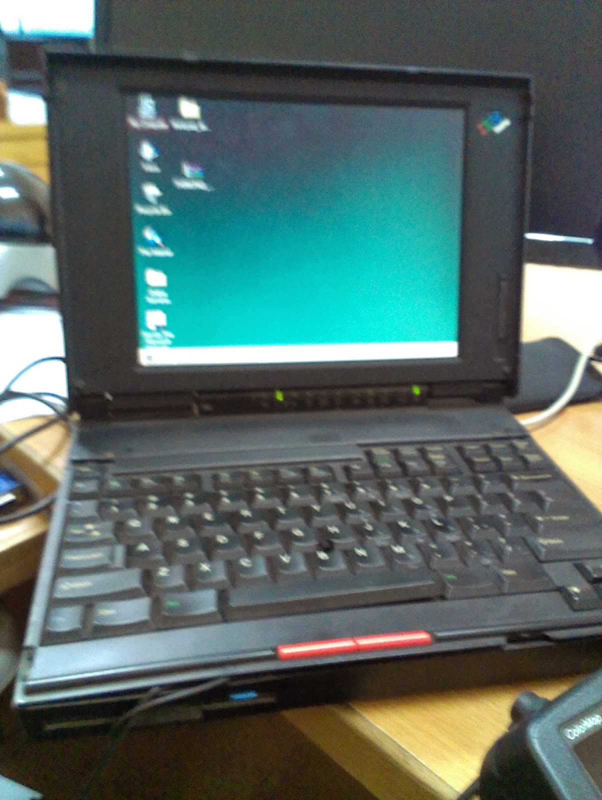
Here are a few pictures of the work in progress. The arduino can be ignored. Its just sitting there on the breadboard from my previous experiment of interfacing the Sonar with it.


Proximity Detection with Sonars using Arduino

In one of my projects, the goal is to detect someone standing in front of an object. My sensors are mounted on this object. I went about figuring out the best way to do this. Turns out there can be several ways of detecting proximity, PIR sensor, IR sensor or Sonar sensor. PIR sensor is not recommended as it only works with moving objects. If the object in front of a camera stops, there is no way of detecting if it is still in front or not (Read http://www.robotoid.com/appnotes/sensors-passive-infared.html). The IR Sensor would require a receiver to be placed at the opposite end of the transmitter for a breach to be detected. In our case this solution won't work as our object could be located in the middle of a crowded space. The solution seems to be using the Sonar sensor. A single or a couple could be used with fine tuned settings to detect an object to within a couple of feet of the object.

So my next experiment is to simply connect a sonar proximity sensor to an Arduino and get signal readings. In order to do that I ordered an HC-SR-04 sensor from EVS Electro.  This is a pretty good distributor if you are based in Islamabad. They can deliver it to you for Rs 200 or you can order and pick it up from their office. I got the sensor for Rs 1200 which is a bit expensive if you compare it to its price on Chinese websites, but then it would be almost the same if you add delivery and tax if any.


This sensor works on the principle of Sonar where ultra sonic sound waves are transmitted which bounce back off an object. Since we know the speed of sound we can figure out the distance by measuring the time traveled by the sound wave to the object and back. The formula for speed is 

          speed = distance / time, 

we can find the distance by 

          distance = speed * time ; 

where speed is the speed of sound and the time is time  taken by the sound wave to travel from the object back to the sensor which would be the total distance of traveling and coming back divided by 2.

The sonar sensor used here has 4 pins. Vcc, Trig, Echo and Gnd. Vcc requires 5 volts so it is connected to the 5v source on the Arduino and the ground is connected as well. This module handles the triggering and the echo sensing on its own. In order to make it work the trigger pin is kept high for 5~10 microseconds, time stamp is taken, after which input is sensed on the Echo pin. As soon as the echo pin goes high another time stamp is taken. Difference between the two timestamps is the total time covered by the pulse transmission, bouncing and returning back. The following is the arduino code for the Sonar Sensor.  The original code can be found at (http://www.arduino.cc/en/Tutorial/Ping). It has been modified to be used with our sensor which has two pins rather than one for the sensor.

/* Ping))) Sensor
 
   This sketch reads a PING))) ultrasonic rangefinder and returns the
   distance to the closest object in range. To do this, it sends a pulse
   to the sensor to initiate a reading, then listens for a pulse
   to return.  The length of the returning pulse is proportional to
   the distance of the object from the sensor.
    
   The circuit:
    * +V connection of the Sonar Sensor attached to +5V
    * GND connection of the Sonar Sensor attached to ground
    * TRIG connection of the Sonar attached to digital pin D10
        * ECHO connection of the Sonar attached to digital pin D11

   http://www.arduino.cc/en/Tutorial/Ping
  
   created 3 Nov 2008
   by David A. Mellis
   modified 30 Aug 2011
   by Tom Igoe
  
   Modified Oct 25th 2013
   by Shamyl B. Mansoor
  
 */

// this constant won't change.  It's the pin number
// of the sensor's output:
const int trigPin = 10;
const int echoPin = 11;


void setup() {
  // initialize serial communication:
  Serial.begin(9600);
  pinMode(trigPin,OUTPUT);
  pinMode(echoPin,INPUT);
}

void loop()
{
  // establish variables for duration of the ping,
  // and the distance result in inches and centimeters:
  long duration, distance1,inches, cm;

 
  digitalWrite(trigPin, LOW);
  delayMicroseconds(2);
  digitalWrite(trigPin, HIGH);
  delayMicroseconds(10);
  digitalWrite(trigPin, LOW);

  //Echo
  duration = pulseIn(echoPin, HIGH);
  distance1 = (duration/2)/29.1;
  // convert the time into a distance
  inches = microsecondsToInches(duration);
  cm = microsecondsToCentimeters(duration);

  Serial.print("duration: ");
  Serial.print(duration);
  Serial.print(": ");
  Serial.print(inches);
  Serial.print("in, ");
  Serial.print(cm);
  Serial.print("cm");
  Serial.println();
   
  delay(500);
}

long microsecondsToInches(long microseconds)
{
  // According to Parallax's datasheet for the PING))), there are
  // 73.746 microseconds per inch (i.e. sound travels at 1130 feet per
  // second).  This gives the distance travelled by the ping, outbound
  // and return, so we divide by 2 to get the distance of the obstacle.
  // See: http://www.parallax.com/dl/docs/prod/acc/28015-PING-v1.3.pdf
  return microseconds / 74 / 2;
}

long microsecondsToCentimeters(long microseconds)
{
  // The speed of sound is 340 m/s or 29 microseconds per centimeter.
  // The ping travels out and back, so to find the distance of the
  // object we take half of the distance travelled.
  return microseconds / 29 / 2;
}

Once you run this sketch and test the sensor, it seems pretty accurate!. Here are some pictures of it measuring distance of an object in front of it.


Wednesday, October 23, 2013

From Russian to English

My friend is an MI 17 pilot in Army Aviation. MI17 is a huge thing which almost looks like an airplane rather than a rotary aircraft. 


His russian friend who proabably came to Pakistan at the time of handing over of the Russian built MI17s gave him a Garmin gpsmap 295 GPS. 

 
(Language converted to English)
Since it was being used by the Russian pilot, it was in Russian language; all menus and functions of the GPS were in Russian. Although my friend used it for basic navigation he couldn't use all the functions. Then one day my friend had to fly his helicopter to the place where I work! Have a look at a snapshot of his landing.


He asked me if I could change the language of the GPS for him and I thought, that should be the easiest thing in the world! Just go to the menus use a little bit of Google translate tool and figure out the menu where the language is changed to English! How foolish of me to think that my friend wouldn't have tried that! Anyway it turns out that you can't simply change the language directly, the firmware with English Language has to be installed and replaced by the Russian Language one. I did some Googling and managed to find the English version of the firmware file for this particular mode.

In order to update the firmware I needed a Serial cable that would connect to the GPS data port. Fortunately I had a similar but older model Garmin GPS with me whose cable I found to be the same for the new one. Now all I needed was a USB to Serial converter as most new computers don't have the old Serial port anymore and I should be able to update the firmware. I thought now it should be easy, except that the update software that was built ages ago in 2001 or 2003 would not work with a USB to serial cable. So I had to find a computer with a serial port. Fortunately again I have a very old IBM thinkpad lying around which I bought during my undergrad years for Rs 2000 only! It is such a rugged laptop that even with my nephew growing up playing games on it, it survived and still works!
It runs Windows 95! Anyway in order to get this to work after years of eating dust in my lab, I had to figure out a way to power it up. Not having an adapter with the required power rating and not knowing the pin configuration of the power port, I fiddled around with the battery input pins and figured out where to connect the ground and the 20 volts. I have a power supply which I used to power it up. 


Finally after powering it up I had to find Hyper Terminal for Windows 7. Hyper Terminal is a simple communications software that allows connecting to other devices using the PC com ports. It is a good software to debug a lot of devices that connect through the com ports via bluetooth or USB ports. Once that was done I transferred my Garmin new firmware and updater program via the serial port using Hyper Terminal. Once I had the files on my old ThinkPad I connected the serial cable of the GPS to the thinkpad and opened the updater application. 


 Voila! It worked and started updating with the new firmware file! And finally when it restarted I had all the menus in English. So we went from Russian to English! My friend is going to use it in his MI17! Mission accomplished.


Wednesday, October 2, 2013

OBD

I have always been a big fan of gadgets and with each passing year, gadgets are becoming cheaper and affordable for most people. Long Live the Chinese! Since the day I had learnt about OBD port in cars, I wanted to play with it. OBD for On board Diagnostics ports are present in most cars manufactured after 1993. These are digital ports that provide vital information from different on board sensors and sub systems of the vehicle. They provide with Diagnostic Trouble Codes which help in identifying the exact problem with the car. Moreover there is a lot of other information that can be used by the owner to see how the car is behaving. With the advent of Chinese made OBD connectors, playing with these ports or at least looking at information available from these ports has become really easy. 

I recently ordered an OBD II Bluetooth module from a guy who sells them on OLX. The bluetooth version only costs Rs 1800 and the Wifi version costs Rs 2800. There are many apps available for the PC, Android and IOS available for download. I have started with Torque which is available on the Android Play store. There is a free lite as well as Pro version available for purchase. The app is quite good with a lot of customization options. So after I received my OBD module, I kind of got busy and didn't really play with until yesterday. I downloaded the Torque app and connected the module to my OBD port in my car and Vola! Data started streaming in! I could see my RPMs, coolant temperature, Speed and a host of other things that I don't even know yet! Anyway now since I have this working, I'm thinking of utilizing my TV screen which is in my car and is hardly used since I don't watch TV or DVDs in my car. So my plan is to utilize that screen but till I get time to that I'm going to be using my Tablet for looking at my Car's data coming in Real time! Its really cool! Have a look at a screenshot of the gauges that I'm using on Torque! Its an image when it is not connected to the OBD of the car, will share one while connected as well later ....


I am using the following OBD scanner Bluetooth Module


Tuesday, October 1, 2013

Playing with Python and OpenCV

For one of my products I need to work with Python and do some image processing. The goal is to do face detection. One of the best things about Python is the support available for it and the number of libraries ported for Python. It hardly took me a day to do face detection using Python and of course, it isn't because of me, but what is already available online. 

In this tutorial I'm going to take you step by step in setting up Python and then setting up OpenCV for python and running an example for loading an image and writing on it. Maybe in the next example I will explain face detection along with an example which by the way is available online from many sources.

Step 1: Downloading python for Windows

The first step is to setup python on your notebook / PC by downloading from the Download Page. In my case I have a 64 bit windows 7 machine so I downloaded the 64 bit version of Python 2.7.5. for windows. You can download for Mac Os or Linux as well. There are two current production versions of python which are 2.7.5 and 3.3.2. If you want to understand the difference between the both and decide which one to work with, have a look at this article


Step 2: Installing Python

The second step is to install Python. If you have downloaded the MSI package it simply installs Python in C:\PythonX where X stands for version number. In my case it is C:\Python27. I would recommend not to change this folder as many libraries that you may install look for this folder, but most detect the installation path of Python from the registry so changing the folder won't be that big a problem.

Step 3: Installing OpenCV

A good repository of python libraries has been maintained by Christoph Gohlke which have also been compiled for 64 bit architecture for windows. Although these are unofficial but they work fine, at least for me. So I downloaded the opencv-python 2.4.6 for python 2.7 compiled for 64 bit architecture (link). You can find your own link on the same page. The downloaded file is an MSI package so simply double clicking on it will run a setup which will automatically detect the Python installation path and install the opencv library in the appropriate directories. I ran into one problem while trying to run my first opencv example. You will see the following error if you don't have Numpy.

from cv2.cv import *
rtError:numpy.core.multiarray failed to import

It requires the Numpy-MKL 1.7.Once you install Numpy from the same repository, openCV will run just fine as it did for me.
  
Step 4: Writing the first example

 Here is a simple python example that will open an image file and write text on it. The example with more details is available (here)


  1. import cv          #Import functions from OpenCV
  2. cv.NamedWindow('a_window', cv.CV_WINDOW_AUTOSIZE)
  3. image=cv.LoadImage('image.png', cv.CV_LOAD_IMAGE_COLOR) #Load the image
  4. font = cv.InitFont(cv.CV_FONT_HERSHEY_SIMPLEX, 1, 1, 0, 3, 8) #Creates a font
  5. x = 10 #position of text
  6. y = 20 #position of text
  7. cv.PutText(image,"Hello World!!!", (x,y),font, 255) #Draw the text
  8. cv.ShowImage('a_window', image) #Show the image
  9. cv.Waitkey(10000)
  10. cv.SaveImage('image2.png', image) #Saves the images

Line 1 imports opencv into the program. If it hasn't installed correctly you will get an error at this line.
Line 2 creates a window which is named a_window. You can change it to any name and the second attribute of the function is self explanatory. It creates an auto sized window.
 Line 3 loads the Image image.png. You can either give the whole path or simply copy the image in the directory of your program. 
Line 4 initializes the font
Line 5 and Line 6 are two variables which contain the position of the text to be displayed on the picture
 Line 7 draws the text in double quotes onto the image. The first argument is the image source and the double quotes is the text, the thirst argument being the position, 4th being the font. 
Line 8 Shows this window onto your screen
Line 9 waits for a key to be pressed. If this line is missing the program simply exits.
Line 10 saves this image into a new file.


You can simply copy paste this code in a notepad application of Windows or I would recommend using  Notepad++. You can also use the IDLE IDE installed with python or there is another one called Pycharm which is licensed. You must save the file with the extension ".py". Windows automatically associates all ".py" extension files to be run with the Python interpreter. You can either run it by double clicking it or open the command prompt on windows, go into Python's directory (C:\Python27) and type "python progarm1.py" on your console (given you have saved the program with this filename). If you have added the installation path of python to your windows PATH variable then you can simple type "python programname.py" in any directory while in the command prompt window.

Once this example is run, the following image is saved as image2.png. Both the original and the modified images are shown below